A Synthesized 1296 MHz TransverterJeff Keyzer, KF6PBP |
 |
My 1296 rig is
based on a design by N6IZW
found on the SDMG
webpage. Basically it uses a Qualcomm synthesized 1152 MHz LO
and 144 MHz IF to give 1296 MHz RF at about 5 watts after the final PA.
Shown here is the front panel, complete with RF, IF, and power connectors, a TX/RX switch with TX indicator for manual switching, and the obligatory power LED. Click on any image to see a full size version. |
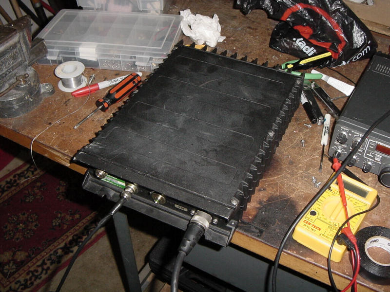 |
The finished enclosure, borrowed from a scrap Qualcomm transceiver. The synthesizer and power supply used in this transverter are part of the original system this enclosure was intended for, making it ideal for housing the whole rig. |
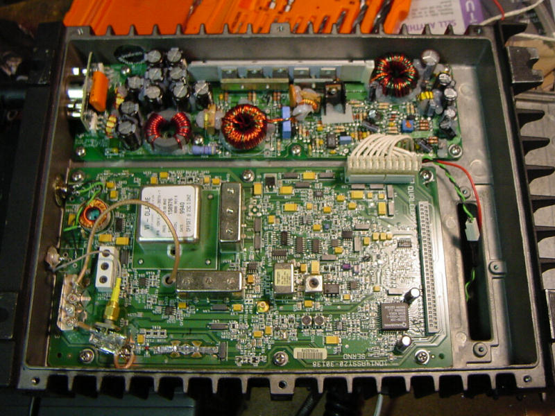 |
Removing the bottom cover unveils the 1152 MHz synthesizer board (lower) and the switching power supply that powers the whole rig from 12VDC (upper). The synthesizer is programmed according to modification instructions here. The 10 MHz TCXO reference is the large white square. |
 |
A closeup of the SRA-11 mixer (top), image reject ceramic resonator filter (right) and microstrip modifications in the LO path (upper left). The image reject filter has about 2dB loss at 1296 MHz and 10-20 MHz or so bandwidth. The image is down by more than 30 dB. |
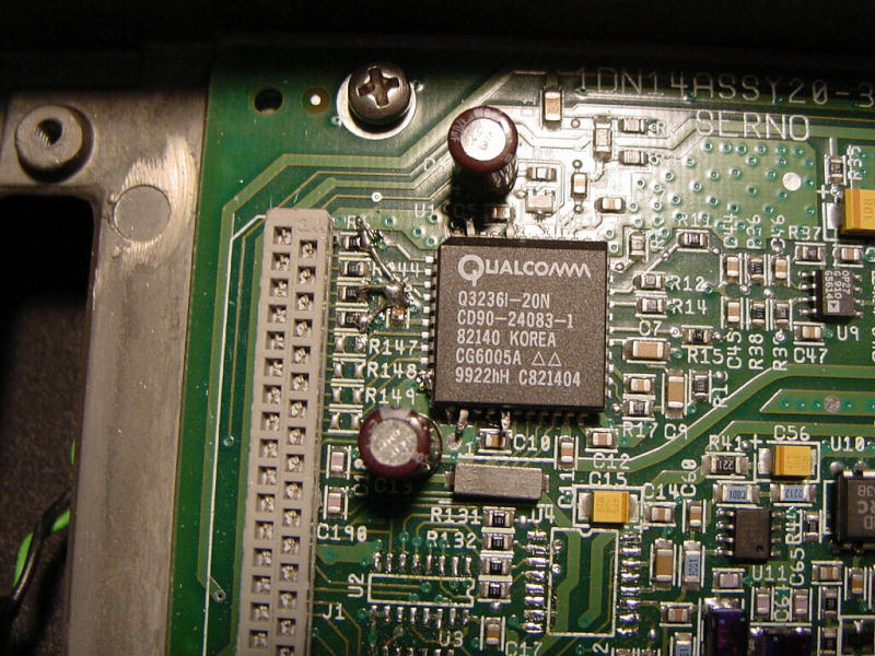 |
A closeup of the Qualcomm 3236 synthesizer chip. Note the lifted pins and ground connections to the left of the chip. This uses a hardware parallel programming mode to reset the LO frequency to 1152 MHz. |
|
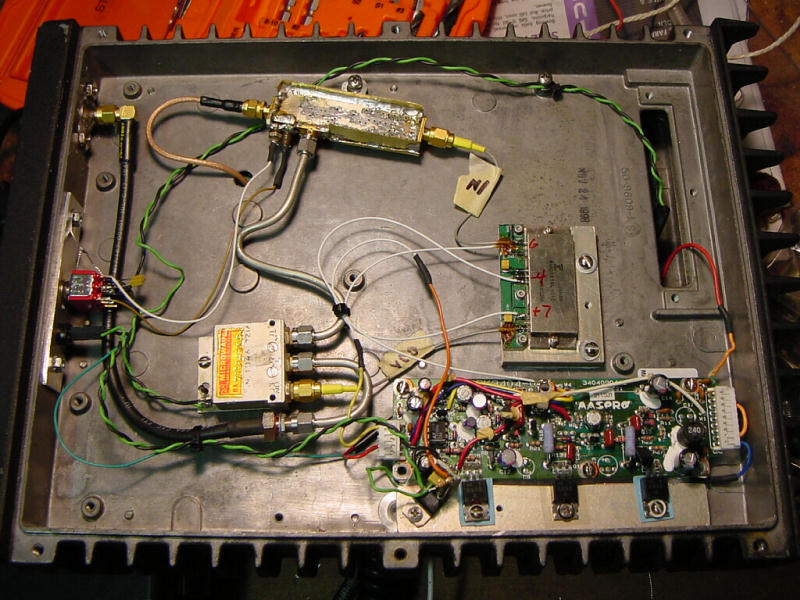
Removing the top cover reveals the 1296 MHz RF components of the transceiver. These include the RX/TX preamps (top), RF relay (lower left of center), and 5 watt PA (modified 1600 MHz PA) with associated power supplies. The RX/TX preamp is part of Qualcomm 10 GHz "gold boards". The receiver has a 3-5 dB noise figure at the moment. I hope to add an LNA in the future to get this down to < 1dB. |
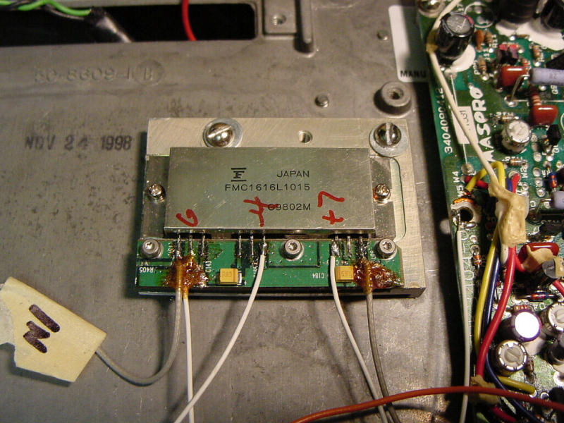 |
A closeup of the hybrid PA module. This module is capable of 10 watts CW with proper heatsinking, but is being run at 5 watts for now to be conservative and avoid blowing such a rare part. |
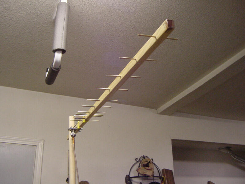 |
I didn't have an antenna already, so I decided to build one. There is a collection of excellent antenna designs on the CLARC website, entitled "Cheap Yagi Antennas for VHF/UHF". The 1296 version is cheap and easy to build (especially thanks to donated parts from Ed, W6OYJ!) and turned out to not only be a lot of fun to put together, but also to perform well. The antenna should have about 13 dBi gain and works like a charm. I have used it to talk to stations as far as 100-150 miles away from an elevated position, with fairly strong signals! All this with a 3-5dB noise figure! |
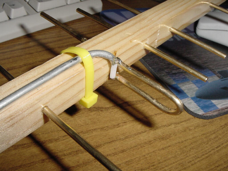 |
Here is a closeup of the driven element showing the hardline coax feedline. All of the elements are made of brass rods which are easy to cut, bend, and solder. The elements are superglued in place. All of the work on this antenna was done by hand and with a pair of dial calipers to insure accurate lengths and spacing. Royce Chow KF6PEO gave me a hand with the construction. |